The design of the buggy was good and unique in the fact that it was Lego with a acrylic base for reinforcement. It was suited for the task but could have been improved in the following ways:
1.The Lego could have been glued together to prevent breakages when the buggy was running.
2.The circuitry could have been built on strip board or PCB (printed circuit board) this would have reduced the size of the buggy, which would make it lighter.
3.The variable resistors could have been mounted on the top of the buggy in order to make tuning the circuitry to follow the lines easier.
4.A cover could have been built in order to cover all the electronic parts using Lego doors in order to access switches and battery compartments.
5.The trolley wheel could have had a better design as it did not suit its purpose and would not swivel as intended causing the buggy to deviate from its intended route.
Overall we believe the design was good and was easy to adapt due to the fact that it was Lego and if something didn’t fit it could be rearranged in order to fit it in, allowing from extensive development during testing.
main1: if pin0 = 0 then ; if the line tracker mode is on
high 0 ;turn left motor clockwise
high 3 ;turn right motor clockwise
Right: if pin1 = 1 and pin2 = 1 and pin6 = 0 then ;if tank meets right turn
low 0 ;stop left motor
low 3 ;stop right motor
high 0 ;turn left motor clockwise
high 4 ;turn right motor anticlockwise
loop1: if pin7 = 1 then ;if front sensor meets the line
low 0 ;stop left motor
low 4 ;stop right motor
else
goto loop1 ;keep turning until front sensor hits line
endif
Left: elseif pin1 = 1 and pin6 = 1 and pin2 = 0 then ;if tank meets left turn
low 0 ;stop left motor
low 3 ;stop right motor
high 1 ;turn left motor anticlockwise
high 3 ;turn right motor clockwise
loop2: if pin7 = 1 then ;if center front sensor hits line
low 1 ;stop left motor
low 3 ;stop right motor
else
goto loop2 ;keep turning until front sensor hits line
endif
Offtrack: elseif pin1 = 0 then
OffLeft: if pin2 = 1 then ;if right sensor hits line
low 0 ;stop left motor
low 3 ;stop right motor
high 0 ;turn left motor clockwise
high 4
loop3: if pin7 = 1 then ;turn right motor anticlockwise
low 0
low 4
high 0
high 3
else
goto loop3
endif
loop4: if pin1 = 1 then
low 0
low 3
high 3
high 1
else
goto loop4
endif
loop5: if pin7 = 1 then
low 3
low 1
else
goto loop5
endif
OffRight: elseif pin6 = 1 then
low 0
low 3
high 3
high 1
loop6: if pin7 = 1 then ;turn right motor anticlockwise
low 3
low 1
high 0
high 3
else
goto loop6
endif
loop7: if pin1 = 1 then
low 0
low 3
high 0
high 4
else
goto loop7
endif
loop8: if pin7 = 1 then
low 0
low 4
else
goto loop8
endif
else
goto OffLeft ;keep reversing until center sensor hits line
endif
elseif pin0 = 1 then
goto main2
endif
endif
goto main1
main2: if pin0 = 1 then ; if the signal tracker mode is on
high 0 ;turn left motor clockwise
high 1 ;turn right motor clockwise
RightSig: if pin7 = 1 and pin2 = 1 and pin6 = 0 then ;if tank meets right turn
pause 100
if pin6 = 1 then
goto Failsafe
endif
pause 2000 ;drive until center sensor is at apex
low 0 ;stop left motor
low 3 ;stop right motor
high 0 ;turn left motor clockwise
high 4 ;turn right motor anticlockwise
loop9: if pin7 = 1 then ;if front sensor meets the line
low 0 ;stop left motor
low 4 ;stop right motor
else
goto loop9 ;keep turning until front sensor hits line
endif
LeftSig: elseif pin7 = 1 and pin6 = 1 and pin2 = 0 then ;if tank meets left turn
pause 100
if pin2 = 1 then
goto Failsafe
endif
pause 2000 ;drive until center sensor is at apex
low 0 ;stop left motor
low 3 ;stop right motor
high 1 ;turn left motor anticlockwise
high 3 ;turn right motor clockwise
loop10: if pin7 = 1 then ;if center front sensor hits line
low 1 ;stop left motor
low 3 ;stop right motor
else
goto loop10 ;keep turning until front sensor hits line
endif
StopRev: elseif pin7 = 1 and pin2 = 1 and pin6 = 1 then
Failsafe: low 0 ;stop left motor
low 3 ;stop right motor
high 1 ;turn left motor anticlockwise
high 4 ;turn right motor anticlockwise
pause 2000
loop11: if pin1 = 1 then ;if center sensor hits line
low 1 ;stop left motor
low 4 ;stop right motor
goto Endprogram
else
goto loop11
endif
Toggle Switch - to swap the buggys programmes running, from following a track, to recognising symbols.
LDR - 4 LDRs gives more to programme, but also a greater sensitivity when calibrated as they can be compared to enable to buggy to make a greater number of decisions based upon the data they provide.
Super-bright LEDs - to light the underside of the buggy and provide the LDRs with a steady light source to compare the track against.
-; Wider research
'We are working on a semi-autonomous vehicle, with pre-programmed instructions following path of recognised symbols.'
'Factories/industries make use of semi-automated vehicles moving goods etc, as well as UAVs.
Enter examples of these into blog, including their level of autonomy. (Do they run non stop 24/7 without human intervention) or does a person have to take over at certain points and revert back to an operator to give it certain instructions? What level would you want, how safe is an entirely autonomous vehicle?'
(Paraphrased instructions.)
Response:
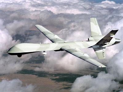
The first semi-autonomous vehicle that sprang to the minds of all our group was the Predator Drone initially introduced by the US-Air force, and now widely used on operations by a number of countries.
The site documenting air-force technology cites the predator as having the following capabilities:
'RQ-1 Predator is a long-endurance, medium-altitude unmanned aircraft system for surveillance and reconnaissance missions. Surveillance imagery from synthetic aperture radar, video cameras and a forward-looking infrared (FLIR) can be distributed in real-time both to the front line soldier and to the operational commander, or worldwide in real-time via satellite communication links. MQ-1, armed with AGM-114 Hellfire missiles, is the multi-role version which is used for armed reconnaissance and interdiction.'
The advantages of such a machine are of course that the human element is almost completely removed, it offers the capability to launch and circle
The advantages of UAVs' as with most other semi-autonomous vehicles, is that the human element is separated from the machine. Taking the predator drone as an example, it can be launched and left to circle until needed, conduct pre-programmed surveillance beaming data back for analysis, or indeed any other mission deemed necessary without needing to return to ground for as many hours as it has fuel to fly. The absence of a pilot on board saves a great deal of weight, as the cockpit, and contained air systems are not necessary.
Reference: all data and conclusions came from reading the following web-page and links
Increasingly the farming industry is looking towards more and more mechanised methods to make their methods easier and more efficient.
Particularly as labour becomes less and less easy to come by, and consumer demand more specific. (e.g. fresh goods NOW!)
The following is quoted from the article whose link is displayed above:
Human-based methods of picking cauliflowers involve about 15 people walking in front of a harvester checking cauliflowers to see if they are the right size, cutting them and then placing them in a hopper. All in a few seconds.
No wonder, then, that mistakes are made and the system is not very efficient.
"At the moment they do one pass and anything that's left is usually left to rot away," said Dr Dudley.
Dr Dudley and colleagues at NPL along with agricultural firm Vegetable Harvesting Systems (VHS) are working on robots that are as fast as humans at working out if a cauliflower is ready to be picked.
One prototype has a multi-axis arm and the other is equipped with a blade that simply cuts and gathers.
The concept to use machinery in farming is not a new one, but as the article goes on to illustrate why it is not yet worldwide, the process is complex to negotiate; for example: even when crops are planted in straight lines and fruit picked off of the trees the challenge is not to destroy the plant itself.
So far, getting robots to be as cheap as human has proved difficult and has focussed interest on making more of the vehicles that are already in use on a farm.
"Take tractors," said Professor Stentz. "They pull an implement and with that they can plough, till and hoe. They can plant, spray chemicals and mow the weeds in between trees."
"There's an opportunity to improve all of that by automating and removing the driver," he said.
In conclusion, in the long run the benefits of using automation will cause the processes to be perfected. By removing the human element, safety will be vastly improved. In the long run, processes will be far more effective.
Autonomous machines, as mentioned earlier with UAVs, can work at full capacity all the time i.e. 24 hours a day without breaks if nessecary, they do not tire or require emotional support, only regular standardised maintenance.
But, as yet this is a long way off - the technology is still relatively new, it still requires human input and guidance, and with its progression will come new bridges to cross, for example at which point do autonomous vehicles cross over into artificial intelligence?
Went to Maplin To ask if they had any stronger reed switches and with the track we've been given their most sensative reed switches wouldnt pick it up.
Reed switches were not sensitive enough for magnetic tape.
Only 3 analog to digital converters on chip.
Actions on Problems
Changed code to suit LDRs.
Chose to not use the ADC's and plan to use the LDR's digitally. If they provide a voltage of over 2.25V then PICAXE will read as logic 1. If under 2.25V then logic 0 will be read.
Future Intentions and Learning Outcomes
LDR's will need to be calibrated for light conditions in the room.
Debug code on buggy testing in order to remove faults and include possible failsafe.
Include extra code for unique additional functions which will be revealed on competition day.
Current Situation
Code for both line following and signal reading modes is complete, tested and fully operational.
Input output variables may change but are easily edited in the code.
J.B - Collated materials for entire construction of buggy. inc. initial chassis design. (Rear wheel drive design proposed for performance!) T.A - Written and tested/de-bugged proposed code for running of buggy within picaxe. - Concept based around reed switches (will they work, if not code can be modified to work with LDRs) C.B - Initial research into electronic components required for circuit and how to link them into proposed coding.
Tasks/Issues presented:
Setup of motors - how are we going to work them? Power Amplifier. They may or may not fit the code and it may need fine tuning once reed-switch output values etc are identified.
Drill lego for motor fitting - J.B
Circuit diagram generation to begin assembly - C.B
In-lecture tasks: Allocated to A. C -> Wider research
'We are working on a semi-autonomous vehicle, with pre-programmed instructions following path of recognised symbols.'
'Factories/industries make use of semi-automated vehicles moving goods etc, as well as UAVs. Enter examples of these into blog, including their level of autonomy. (Do they run non stop 24/7 without human intervention;) or does a person have to take over at certain points and revert back to an operator to give it certain instructions? What level would you want, how safe is an entirely autonomous vehicle?' (Paraphrased instructions.)
Tools required for next lecture:
Hand Drill Small Saw File Super-glue!
Future group meetings:
Group Brainstorming session for buggy casing. (Lego building/experimentation session!)
Attendees: C. Bond A. Compton J. Baddeley T. Anderson
Project Manager - A. Compton Chief Designer - J. Baddeley Software Engineer - T. Anderson Electrical Engineer - C. Bond
Team Name:
ABBA
(Amy,Baddeley,Bond,Anderson)
Mission Statement - ?
- To do:
Inspiration - initial ideas - running of project - deadlines Snippets of code, circuit diagrams, videos/photographs, as well as specialised requested research.
- Design Brief: Build and test an intelligant buggy. Should have 2 modes of operation - selectable by switch. Should be capable of following a black line and recognising junctions and the end of the 'road.' The dark line will be a magnetic strip 20mm wide.
Specified Tasks: build buggy
Implied Tasks: design circuit board identify components shassis power supply drive system picaxe programme
- Test sensitivities and tolerances of available sensors. - Generate chassis, bodywork etc. - LEGO? - Research available/similar projects, whats been done before? - Theme? Moon buggy - Sports car - Tank - Aircraft taxi-ing? - Reed switches.